


Repairing & Strengthening Bridge Girders in Turkey
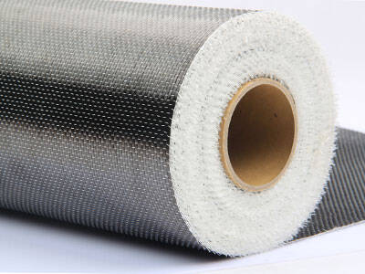
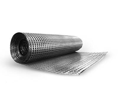
Using Carbon Fiber CFRP
This RC bridge, situated in Turkey, spans a small river and has been a key local traffic artery for over 30 years. Years of continuous traffic load – from daily passenger cars, trucks, and occasional heavy - duty vehicles – combined with environmental erosion like freeze - thaw cycles in winter and humidity in summer

This RC bridge, situated in Turkey, spans a small river and has been a key local traffic artery for over 30 years. Years of continuous traffic load – from daily passenger cars, trucks, and occasional heavy - duty vehicles – combined with environmental erosion like freeze - thaw cycles in winter and humidity in summer, had taken a toll. Initial visual inspections revealed multiple cracks in the girders, some up to 5 mm in width, and signs of concrete spalling at the bottom of the girders. Structural health monitoring data showed that the deflection of the girders under peak traffic loads had increased by 20% compared to design standards, indicating a decline in load - bearing capacity.
Damage
1) Cracking: The cracks were mainly flexural cracks at the bottom of the girders and shear cracks near the supports. Flexural cracks occurred due to excessive bending stress, as the girders struggled to bear the increased traffic loads. Shear cracks were a result of insufficient shear resistance, especially in areas where the load distribution changed, like near the supports.
2) Concrete Spalling: This was caused by the corrosion of internal steel rebars. As rebars rust, they expand, exerting pressure on the surrounding concrete, leading to spalling. This not only weakened the concrete cover but also exposed the rebars to further corrosion, creating a vicious cycle.
3) Deflection Increase: The combined effect of concrete creep, rebar yielding, and crack development led to an increase in girder deflection. This not only affected the driving comfort but also indicated a potential for structural failure under extreme loads.
Inspection and Assessment (In - depth)
1) Non - Destructive Testing (NDT): Advanced NDT methods were employed. Ultrasonic testing was used to map the internal crack distribution and rebar corrosion levels within the girders. Infrared thermography helped identify areas of delaminated concrete and poor rebar - concrete bonding. Strain gauges were installed on the girders and rebars (where accessible) to measure the actual stress distribution during peak traffic hours.
2) Load Testing: A static load test was conducted, where calibrated weights were placed on the bridge deck to simulate different traffic loads. The deflection, strain, and crack propagation were closely monitored. This data was used to fine - tune the CFRP strengthening design and ensure its effectiveness.

Carbon fiber reinforced polymer (CFRP) was selected after a thorough evaluation of various strengthening methods, including traditional concrete jacketing and external steel plate bonding.
Surface Preparation (Detailed)
Concrete Repair: For areas with concrete spalling, the damaged concrete was carefully chipped away to expose sound concrete. A high - strength, rapid - setting repair mortar was used to restore the concrete surface to its original profile. The repair mortar was chosen for its good bonding properties with both the existing concrete and the subsequent CFRP adhesive.
Cleaning and Profiling: The entire surface of the girders was cleaned using high - pressure water jets to remove dirt, oil, and loose particles. Then, the surface was profiled to create a slightly rough texture, which enhanced the bond between the concrete and the CFRP adhesive. Special attention was paid to the crack areas, where the surface was meticulously prepared to ensure proper CFRP adhesion across the cracks.
CFRP Application (Step - by - Step)
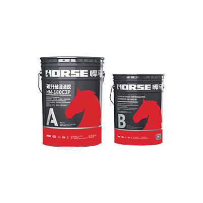
Adhesive Preparation: The two - component epoxy adhesive was mixed in strict accordance with the manufacturer's instructions. The mixing ratio was carefully controlled, and the adhesive was allowed to stand for the recommended pot life to ensure proper curing.
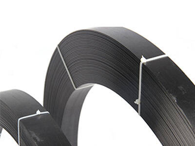
CFRP Cutting and Placement: The CFRP sheets were cut using diamond - tipped tools to the precise dimensions determined by the design. For flexural strengthening, the sheets were carefully aligned along the length of the girders, ensuring that they covered the tensile stress zones. For shear strengthening, the U - wraps were positioned and wrapped around the girders, with the overlap areas carefully bonded to ensure continuous shear resistance.
Bonding and Rolling: The adhesive was evenly applied to the prepared concrete surface and the back of the CFRP sheets. The sheets were then pressed onto the surface, and a roller was used to ensure full contact, remove any air bubbles, and achieve a uniform bond thickness. The rolling process was repeated several times to ensure optimal adhesion.
After CFRP strengthening, a repeat static load test showed that the maximum deflection of the girders under the same peak load was reduced by 30%, bringing it back to within the design limits. The bending stress in the girders, measured by strain gauges, was also reduced by 20%, indicating that the CFRP had effectively shared the load with the original RC structure.
